Table of Contents
Example: Serial
These examples send strings over the serial interface and display what they receive. The proper operation of the interface can be tested with a loop back on the screw terminals of the ZSOM-Control.
Project: ZSOM-Control_Serial.lvproj. In LabVIEW, open Help → Find Examples and search for “ZSOM”. The project contains two RT VIs:
| VI | Interface | Documentation |
|---|---|---|
Serial_RS232_RT_main.vi | RS232 | RS232 |
Seriel_RS485_RT_main.vi | RS422 or RS485 | RS422 / RS485 |
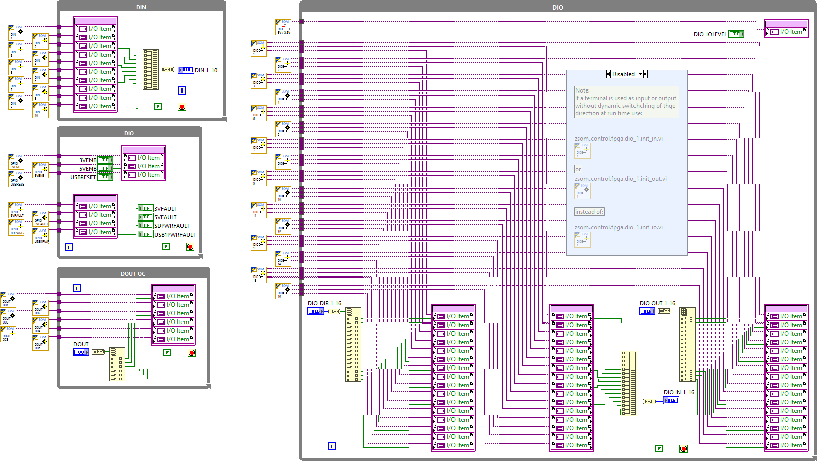
The examples do not need a specific FPGA VI. They only need the pin definition from the CLIP, which is compiled with the FPGA VI (Serial_FPGA_main.vi).
RS232
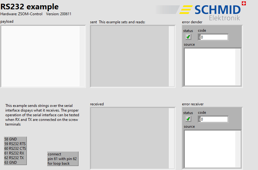
RT code: front panel (RS232 VI)
Loop back: connect pin 61 (RS232 RX) with pin 62 (RS232 TX). Pin 58 and pin 63 are GND, pin 59 is RTS and pin 60 is CTS, see the ZSOM-Control pinout.
RS422 / RS485
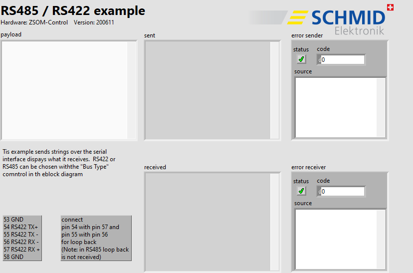
RT code: front panel (RS485 / RS422 VI)
RS422 or RS485 is chosen with the “Bus Type” control in the block diagram. When RS485 is chosen, the wire mode of the serial port is set to 2-wire with automatic direction control.
Loop back: connect pin 54 (RS422 TX+) with pin 57 (RS422 RX+) and pin 55 (RS422 TX−) with pin 56 (RS422 RX−). Pin 53 and pin 58 are GND. In RS485 mode the loop back is not received.
Front panel
| Control / Indicator | Function |
|---|---|
| payload | The string that is sent |
| sent | The string that was sent |
| received | The string that was received |
| error sender / error receiver | Error cluster of the sender and the receiver |
How it works
- RT: The serial port is opened via VISA with 115200 baud, 8 data bits, no parity, 1 stop bit and no flow control. The VISA resource is ASRL2::INSTR for RS232 and ASRL6::INSTR for RS422 / RS485. If the port is still open, it is closed first.
- Sender: Sends the payload followed by
\nevery 100 ms. - Receiver: Reads the bytes at the port until
\nor\ris received or until a timeout occurs. The packet is shown in received.
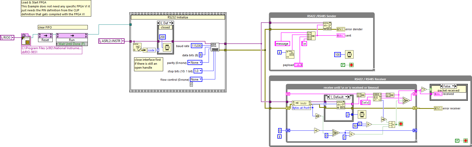
RT code: block diagram (RS232 VI)
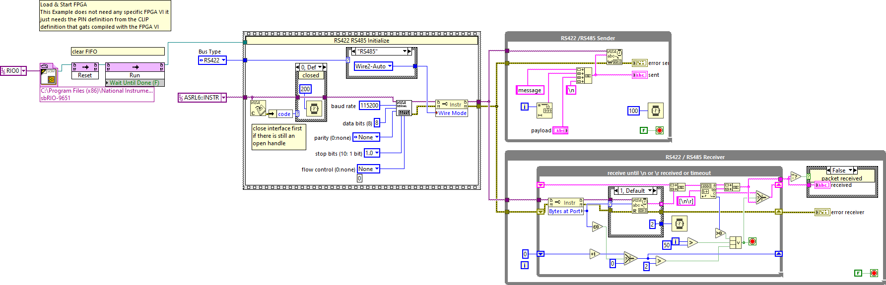
RT code: block diagram (RS485 / RS422 VI)
FPGA code: block diagram