Table of Contents
Example: Mini RTC
With this example you can read and write the system time and the time of the precise real time clock on the ZSOM-Mini board. You can also set alarms in the precise RTC to wake up the ZSOM-Mini from power off mode.
Project: ZSOM-Mini_RTC.lvproj. In LabVIEW, open Help → Find Examples and search for “ZSOM”.
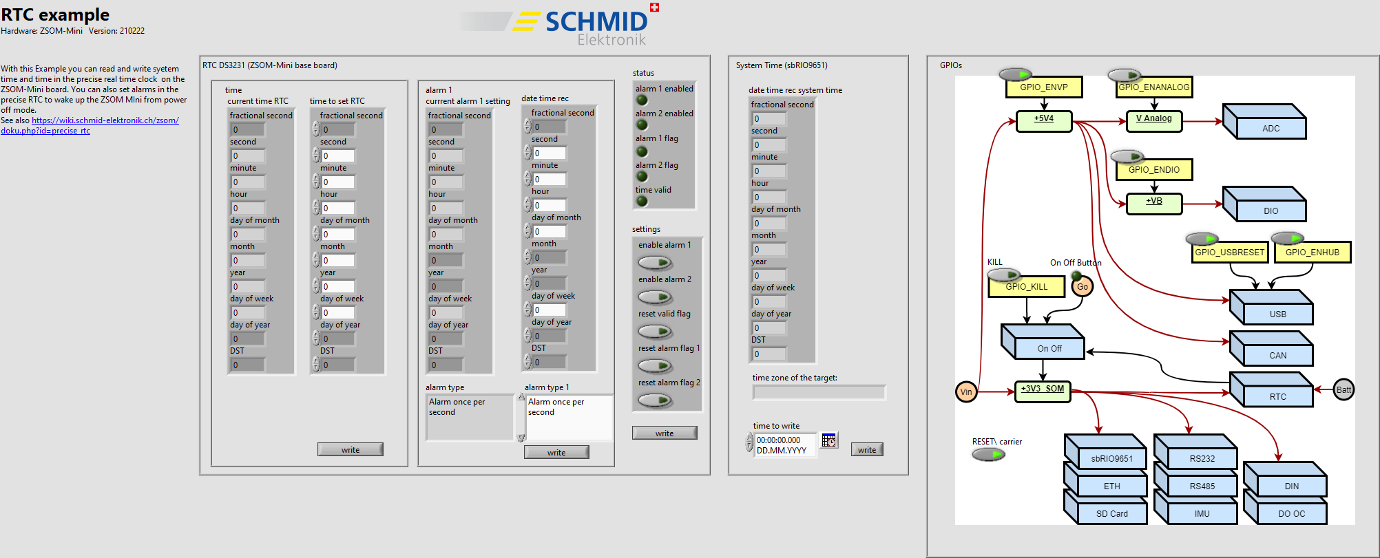
RT code: front panel
Front panel
| Section | Function |
|---|---|
| RTC (ZSOM-Mini base board) | Shows the current time of the RTC (time) and writes a new time (time to set RTC). Alarm 1 and alarm 2 can be set with the alarm type, for example Alarm once per second. |
| status | Shows whether alarm 1 and alarm 2 are enabled, the alarm flags and whether the time is valid |
| settings | Enables the alarms and resets the valid flag and the alarm flags |
| System Time (sbRIO9651) | Shows the system time of the target, its time zone and writes a new system time |
| GPIOs | The GPIOs that control the power distribution, see Example: Mini GPIO |
How it works
- FPGA (
RTC_FPGA_main.vi): Implements the TWI bus to the RTC on the base board and provides the GPIOs. The RT exchanges the data with the bus through FIFOs. - RT (
RTC_RT_main.vi): Loads and starts the FPGA and runs three parallel loops (wait time 500 ms): System Time, RTC (read the current time, write the time, write alarm 1, set the control register) and GPIOs. The writing actions are started with the buttons write.
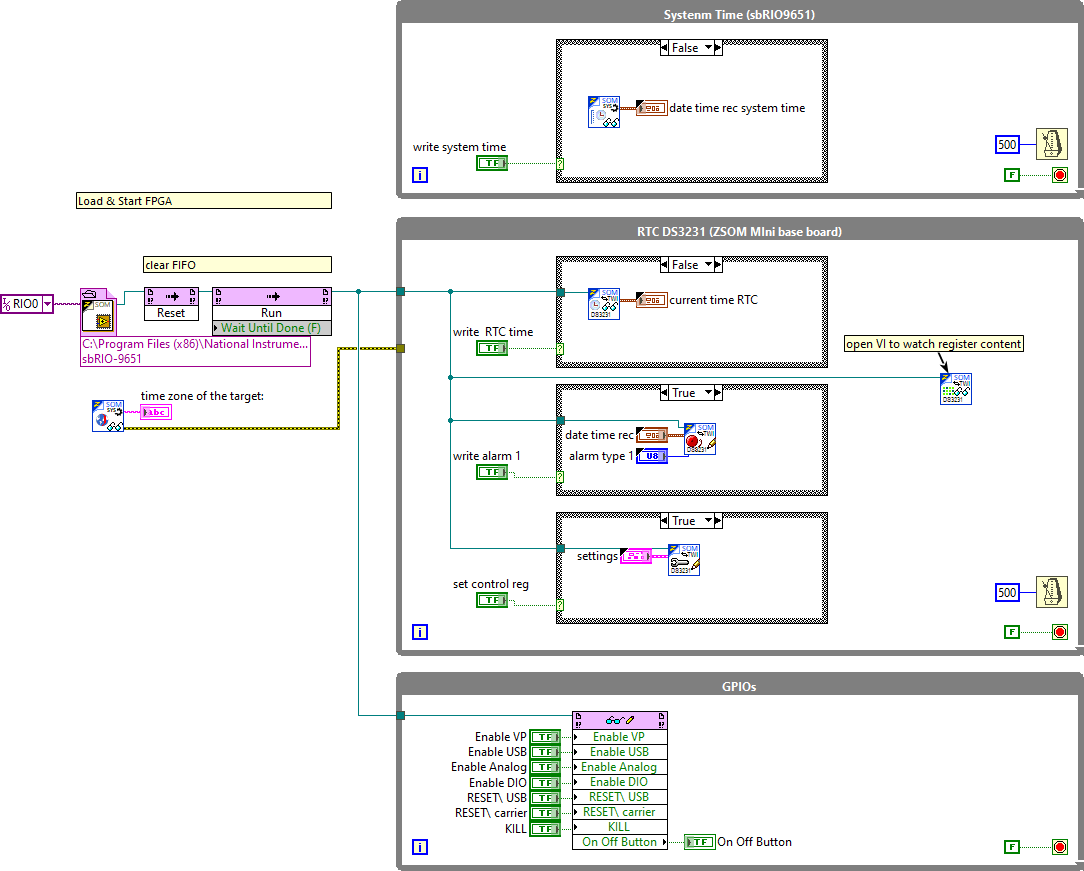
RT code: block diagram