Table of Contents
ZSOM Mini Power and GPIOs
On the ZSOM-Mini, individual board regions can be powered and reset separately. This is controlled via GPIO lines from the sbRIO-9651, so software can selectively enable, disable or reset specific parts of the system. By default, most board regions are disabled and must be activated by the application.
Additionally, the Kill GPIO, the Go input and alarms set on the precise RTC control whether power is applied to the board.
The following graphic shows the GPIOs and the board regions they control in a simplified schematic view:
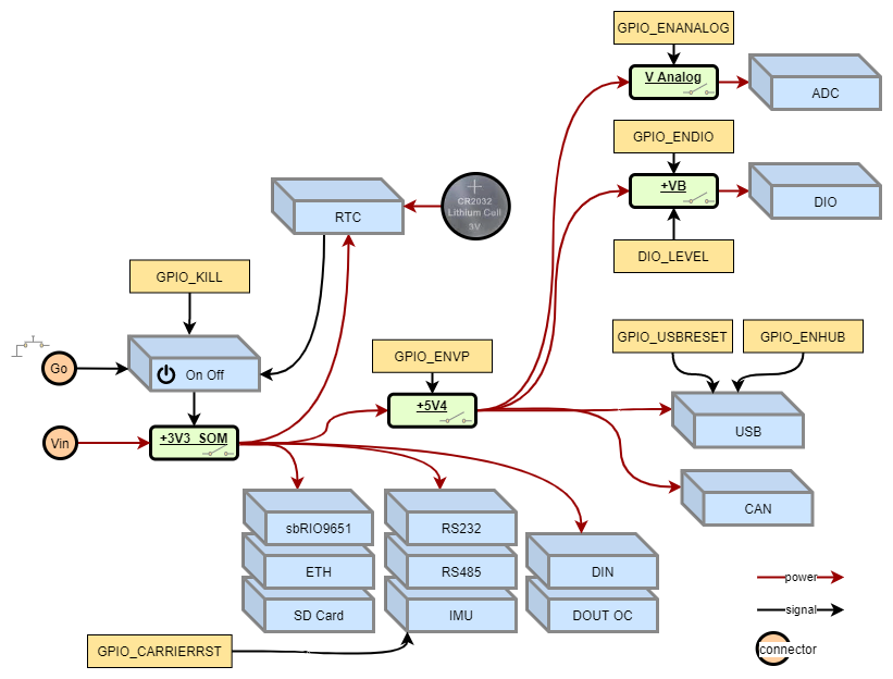
Examples:
- To use the general purpose high speed I/O (DIO) the ZSOM-Mini must be powered on and the GPIOs ENVP and ENDIO have to be activated.
- To use the rugged digital input (DIN) the ZSOM-Mini must be powered on. No further GPIOs have to be set.
See also the ZSOM-Mini_GPIO.lvproj example (and peripheral-specific examples), which lets you interact with all GPIOs that control the peripherals.
Example: enabling USB
The following FPGA code shows how the USB port is enabled on the ZSOM-Mini (GPIO_ENVP, GPIO_ENHUB and GPIO_USBRESET must all be set to True):

GPIO reference
| OUTPUTS | ||
|---|---|---|
| Name | Function | Polarity |
| ENVP | Enables the internal 5V supply that delivers power to USB device, CAN, general purpose high speed I/O (DIO) and analog in. | TRUE = power is enabled |
| ENDIO | Enable power for general purpose high speed I/O (DIO) | TRUE = power is enabled |
| DIO_LEVEL | Choose logic levels for general purpose high speed I/O (DIO) input and output functionality | TRUE = 3.3V FALSE = 5V |
| ENANALOG | Enable power for analog in | TRUE = power is enabled |
| ADC RANGE | Switch the input range of all analog in channels. Is part of ADC FPGA driver VIs | TRUE = ±5V FALSE = ±10V |
| ENHUB | Enable power for USB device | TRUE = power is enabled |
| USBRESET | Reset USB device hub | FALSE = USB hub goes to reset state |
| CARRIERRST | Reset IMU on ZSOM Mini | FALSE = reset is active |
| KILL | Kill signal to cut the power of ZSOM-Mini | TRUE = power off |
| LED USER | Controls the status of the FPGA LED | TRUE = light on |
| INPUTS | ||
| Name | Function | Polarity |
| SD PWR FAIL | Error indicator of board region | |
| USB PWR FAIL | Error indicator of board region | |
| ON OFF BUTTON | Reads the status of the power on input (GO) | TRUE = pressed |