Example: SmartBattery
This example reads information such as the remaining capacity from a smart battery fuel gauge via the TWI bus. The bus is implemented with two DIOs, see also I2C.
Project: ZSOM-Control_SmartBattery.lvproj, VI SmartBattery_RT_main.vi. In LabVIEW, open Help → Find Examples and search for “ZSOM”.
Connection
- Connect the clock line to DIO 1 with a 4.7 kΩ pull-up resistor to 3.3 V or 5 V.
- Connect the data line to DIO 2 with a 4.7 kΩ pull-up resistor to 3.3 V or 5 V.
- Connect the battery GND to GND. This is not necessary if the ZSOM-Control is powered by the battery.
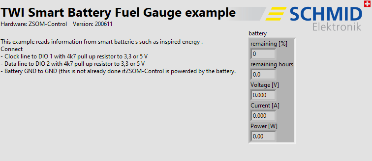
RT code: front panel
Front panel
| Indicator | Function |
|---|---|
| remaining [%] | Remaining capacity in percent |
| remaining hours | Remaining operating time in hours |
| Voltage [V] | Battery voltage |
| Current [A] | Battery current |
| Power [W] | Battery power |
How it works
- FPGA (
SmartBattery_FPGA_main.vi): Implements the TWI bus on the lines DIO 1 (clock) and DIO 2 (data). The RT exchanges the data with the bus through FIFOs. - RT (
SmartBattery_RT_main.vi): Loads and starts the FPGA and then reads the battery values in a loop (wait time 500 ms) withFuelgauge.vi. The SubVITWIdevice.SmartBattery.viaccesses the registers of the smart battery.
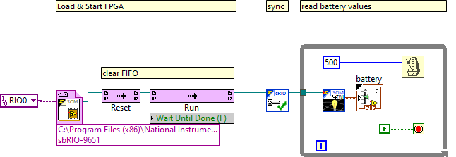
RT code: block diagram